Concrete slab reinforcement design and code checks can be performed based on the following codes:
Note:
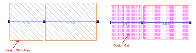
The reinforcement design is calculated based on the Design Strips which are defined by the Support Lines. See Elevated Slabs - Modeling for a full description of how to model the Support Lines and Design strips. Within a Design Strip, there are Auto-generated Design Cuts that are "slices" thru the design strip perpendicular to the Support Line. The Design Cut finds all the forces across it's length and then finds adequate reinforcement for these forces. In the example below, there are 50 Design Cuts per span. The program will envelope all the reinforcement requirements per span and come up with a final design. The reinforcement spacing and size are defined in Slab Design Rules spreadsheet. The reinforcement design checks the analytical requirements, minimum ratios and detailing requirements.
The number of Auto Design Cuts are defined when you draw the Support Line and can be modified in the Slab Design Strip spreadsheet. The design cuts will start at the face of the columns with the exception set by ACI 318-14 Section 8.11.6.1 (ACI 318-11 13.7.7.1) specifies that the design should be not farther away from than 0.175*L1 (L1 is the span).
Two rebar design options are available, namely the Construction method and the Theoretical method, for the design of the slab rebar. The Construction method, which is the default method employed by the program for a significant period, determines the design of the slab based on an integer number of rebar. This method operates under the assumption that if the strip width divided by rebar spacing is not an integer, an additional rebar will be provided to guarantee the presence of a rebar at each end of the design strip. On the other hand, the Theoretical method is a new method added later that enables the program to calculate the rebar area based on the average value, where the rebar area equals As (single rebar) multiplied by the Strip Width divided by Spacing. However, it is crucial to note that this method may not always result in an integer number of rebar so unlike the Construction method, the results for Theoretical method will have no info of rebar amount. You can select different rebar design options in Global Model Setting.
Slabs may be analyzed and designed using traditional reinforcement bars or welded deformed wire reinforcement (WWR). WWR can be enabled by going to the Global Model Settings and checking the “Include Welded Wire Reinf.” option in the Concrete tab.
Note:
Welded wire reinforcement is only available for Elevated Slabs.
Only ASTM A1064 deformed bar sizes are available.
Development length is conservatively calculated in the similar fashion as traditional reinforcement bars. Ψw factor is conservatively ignored which reduce the development length due to contribution of “welded intersections”.
Because a design strip has multiple cuts we need to first consider each cut and then take the enveloped value for the cuts for the overall strip.
For each design cut:
Report Decimal Spacing. The cut will fail anyway because Req’d spacing was below what’s allowed, so who cares that we report a decimal value for a failing cut. Report As from Step 1.
Once this is complete we have a rebar spacing and As for each cut.
For each design strip then r eport the smallest value of Spacing from all of the Design Cuts.
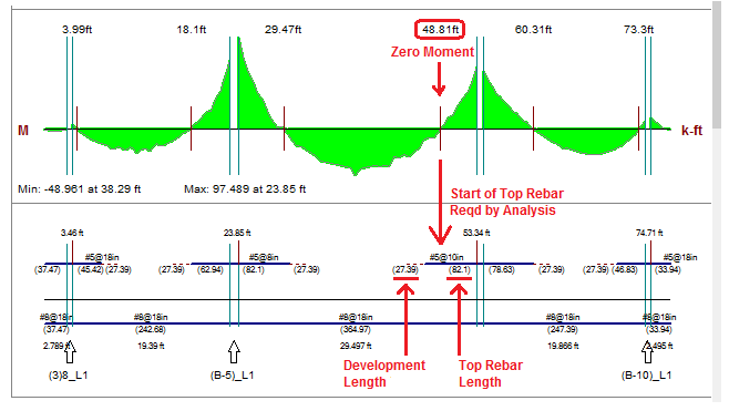
The top reinforcement is shown with a heavy blue line and the length is listed below in parenthesis. The rebar is measured from the center-line of the column to the end of it's required length. The development length is shown beyond the top rebar length and it's indicated by the red dashed line at the end and the length is shown in parenthesis below.
The Top Rebar length is determined by the following steps:
Step 1: Find the required length by analysis determined by the point of zero moment. This location indicates the no demand for tensile reinforcement to resist flexure. The zero moment location is indicated on the moment diagram as a vertical red line and the location of that line is listed above. This dimension is an overall dimension from the start of the support line to that point.
Step 2: The development length is calculated using ACI 318-14 Section 25.4.2 (ACI 318-11 Section 12.2.2, CSA A23.3-14 Section 12.2.2). Check the development length is longer than the minimum required by ACI 318-14 Section 7.7.3.3 (ACI 318-11 Section 12.10.3, CSA A23.3-14 Section 12.10.4), if not use this value as the development length.
Step 3: Add the required by analysis length (Step 1) and development length (Step 2) and check that it meets the minimum extensions listed in ACI 318-14 Fig 8.7.4.1.3(a) (ACI 318-11 Fig 13.3.8, CSA A23.3-14 Figure 13.1). If the total minimum length is not met then the additional length will get added to the length required by analysis.
Note:
The example shown below demonstrates the case where the minimum was not met and the top rebar length indicated with a heavy blue line is longer than required by analysis.
The bottom bars are considered continuous along the entire Design Strip throughout the entire support line. The ACI allows for a certain amount of reinforcement to be discontinuous however at this time RISA is not indicating any other length than fully continuous.
Note:
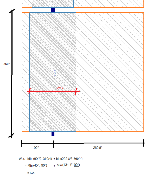
The image below describes how the program calculates the Column Strip width (wcs). The variables l1 and l2 are also described above. This drawing shows how the Design Strip can be tapered and the equation accommodates the taper and non-tapered Design Strip. The width of the Column Strip is not allowed to vary along the span. The width of the Mid-Strip Right and Mid-Strip Left may vary.
Note:
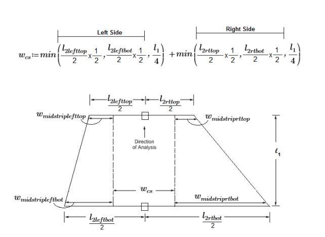
Example calculation: This shows how the Column Strip width is calculated for a non-tapered Design Strip.
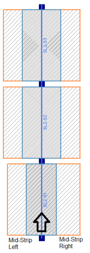
The Mid-Strip is calculated by centering the Column Strip over the middle of the Support Line and the remainder is the Mid-Strip on each side. The actual width of the Mid-Strip for each side is listed in the Design Cut Detail Report.
The Mid-Strip Left and Mid-Strip Right are defined by the way the Support Line is drawn. Below is an example that shows the Support Line is drawn from the bottom to the top and the Support Line is numbered accordingly (SL1 at the bottom, SL3 at the top). From the vantage point of the start of the Support Line, the Mid-Strip Right falls to the right of the Support Line and the Mid-Strip Left falls to the left of the Support Line.
Concrete slabs are susceptible to two different types of shear failure:
One Way Shear can cause a localized shear failure along a plane perpendicular to the direction of the shear. This type of shear is checked across the total design strip width (column strip plus middle strip) as part of the Design Cut. The total amount of shear for each Design Cut is determined through finite element analysis, and is compared against the shear capacity of that cut. Because it is not possible to provide stirrup shear reinforcing for concrete slabs, the plain concrete shear strength is used. RISAFloor ES automatically calculates the ratio of shear force to shear capacity for each Design Cut, and produces a warning if that value exceeds 1.0 anywhere in the model.
When ACI 318-19 is selected, the shear strength of concrete (Vc) uses equations in Table 22.5.5.1. Note that slabs do not have shear reinforcement (Av≤Av,min), Vc is calculated by the equations (c) in the table. ACI 318-19 code suggests ρw may be taken as the sum of the areas of longitudinal bars located more than two-thirds of the overall slab depth away from the extreme compression fiber. Therefore, RISA calculates ρw as the sum of the areas of longitudinal bars on the tension face of the slab.
When other ACI 318 editions are selected, the shear strength of the concrete alone is limited to the standard 2*λ*sqrt (f'c) equation from ACI 318-14 Section 22.5.5.1 (ACI 318-11 Section 11.2.1.1) and does not use the more detailed calculations of ACI 318-14 Table 22.5.5.1 (ACI 318-11 Section 11.2.2).
Two Way Shear(Punching Shear) can cause a shear failure consisting of a plane through the slab which forms a closed circuit around a support or a location of high load concentration. This type of shear is checked for each column that supports the slab, and for any columns which terminate on the slab without a column below. With this type of failure the column "punches" through the slab, leaving a hole in the slab and allowing the slab to move vertically relative to the column. Because it is not possible to provide stirrup shear reinforcing for concrete slabs, the plain concrete shear strength is used. The most common method of addressing punching shear is to increase the perimeter of the failure plane, thereby increasing the amount of concrete to resist the shear. This can be addressed either by using a larger column, or by thickening the slab in an area around the column (known as a Shear Cap). RISAFloor ES automatically calculates the ratio of shear stress to shear capacity around each column and produces a warning if that value exceeds 1.0 anywhere in the model.
Refer to the Punching Shear - Design and the Punching Shear - Results topics for more information about punching shear checks around a column.
Note:
Post Tensioned Reinforcement design is not currently supported in RISAFloor ES.
Skip Loading is not currently considered on a two-way slab. The skip loading can be applied to a Beam Supported floor, see Skip Loading for more information.
Creep/Long Term Deflectionwill only be analyzed for concrete floor slabs when the User Defined method is selected for the reinforcement design. Creep/Long Term Deflection is not currently analyzed in RISAFloor ES for Concrete Floor slabs when using the design strip method. In this case, the program will check point deflection based on the cracked or uncracked moment of inertia. For further information on the deflection calculations, see theDeflection topic.